
Dipping your wheels off the edge of a well-built jump and soaring through the air is one of the most exhilarating experiences in mountain biking. Whether you’re aiming for small tabletops or dreaming of bigger air, understanding the principles behind Bike Jumps is crucial for both builders and riders. While massive gaps and towering heights might not be for everyone, even smaller jumps demand respect and a solid grasp of the physics involved. Going too slow or too fast on a jump can lead to harsh landings, or worse. Many jump builders rely on intuition and trial and error, shaping and reshaping until it feels right. But what if you could approach jump building with more precision, relying on science and a little math to minimize guesswork and maximize ride time?
This article delves into the science behind bike jumps, exploring the key mathematical and physical principles that govern their design and execution. We’ll move beyond trial and error and into a world where understanding projectile motion, landing angles, and transition curves can help you build safer, more predictable, and ultimately more enjoyable bike jumps. By applying a bit of math and physics, you can spend less time moving dirt and more time catching air. Even professional stunt riders and record-breaking jump events rely on these principles, consulting physicists and engineers to ensure success and safety. So, before you grab your shovel, let’s explore the science that can elevate your bike jump game.
Equivalent Fall Heights: Designing for Softer Landings
One of the primary goals in bike jump design is to create landings that minimize impact. The concept of Equivalent Fall Height (EFH) is crucial here. Imagine landing from a certain height – the EFH aims to replicate the impact force of that fall, regardless of the actual jump height or distance. Ideally, a well-designed landing ramp should maintain a consistent or decreasing EFH throughout the landing zone. This is typically achieved by making the landing ramp steeper further down the slope, mirroring the parabolic flight path.
In the ski industry, a maximum EFH of around 4-5 feet is generally considered safe. This means the impact force upon landing should be equivalent to falling from no more than 4.9 feet (1.5 meters). While the ideal EFH for bikes might be slightly higher due to suspension, rider safety should always be the priority. It’s crucial to consider what the human body can safely handle in a worst-case scenario, rather than just what the bike can endure. Research and established guidelines, like those found in the PDFs mentioned later, offer a safer approach. EFH is calculated based on the kinetic energy of the vertical landing velocity divided by mg. Therefore, the landing ramp should steepen as distance increases to accommodate increasing velocities. Landings exceeding an EFH of 4.9 feet pose a significant risk of knee injuries across various sports, including skiing, snowboarding, and biking.
For a detailed, step-by-step guide to calculating EFH and applying these principles in jump design, refer to resources like the Jump Building Guide.
Projectile Motion and Newton’s Laws: The Physics of Flight
The flight of a bike jump is governed by the fundamental laws of motion, particularly the principles of projectile motion. Understanding these principles can transform your approach to jump building and riding. For many, the realization that physics class has real-world applications hits home when considering bike jumps, skateboard ramps, or even golf. This section translates those physics lessons into practical knowledge for bike jump enthusiasts.
The equations of projectile motion describe the trajectory of an object launched into the air, considering factors like initial velocity, launch angle, and gravity. To simplify jump design, a bike jump calculator is provided below. This tool can help estimate jump range, height, and air time based on launch speed and angle. While math might seem daunting to some, it’s a powerful tool for optimizing jump design and reducing trial-and-error. Embrace the math – it can send you higher and further, and ultimately make jump building more efficient and predictable. While no calculator can eliminate all risks or guarantee perfect results due to variables like rider behavior and terrain, it significantly improves the odds of success.
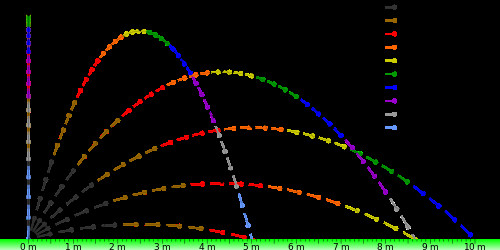 Parabolic Jump/Projectile Trajectories showing different launch angles and range
Parabolic Jump/Projectile Trajectories
The flight path of a bike jump, both off a ramp and off a drop, ideally follows a parabolic curve. However, in reality, factors like air resistance (drag) distort this perfect parabola. Drag forces mean that velocity and acceleration are not constant, but continuously changing, making the actual flight path deviate from ideal projectile motion.
Interestingly, as illustrated above, launch angles of 30 degrees and 60 degrees (and other complementary angles in light gray) can yield the same horizontal distance (range, R) with the same initial velocity, but result in significantly different heights. A 45-degree launch angle maximizes range. This isn’t arbitrary; it’s a direct result of the laws of physics. Experiment with the calculator below using 30 and 60-degree angles to observe this phenomenon. You can also test this practically by building two ramps side-by-side with identical heights and landing areas. For the 60-degree ramp, a slightly steeper landing might be beneficial, or consider angles between 30 and 60 degrees, perhaps 45 degrees for both. (See the Excel sheet image, if available, for a tabular representation of these parabolic relationships.)
When designing jumps and rollers, prioritize smoothness, especially for bikes with longer wheelbases like large 29ers (around 46 inches or more). Tighter transitions can be hazardous at higher speeds, and excessive centrifugal force (G-forces) can stress both bikes and riders. Incorrectly designed transitions can even cause riders to be thrown forward. While flips might be intentional for advanced riders, controlled design is paramount for safe progression. Consulting engineers or experienced builders is advisable for complex features, as relying solely on intuition can lead to dangerous outcomes.
Tall jumps, rollers, or grade reversals can effectively reduce speed, allowing for the strategic placement of subsequent features to control speed and flow. These considerations lead to exploring concepts like the golden ratio and isochronic curves, as well as clothoids, which have significant implications for trail and bike feature design, particularly in relation to wheel size.
Imagine a story about a user who successfully jumped cars using the principles learned from a jump calculator. This highlights both the power of these principles and the importance of safe application. While the calculator assumes simplified conditions, real-world jump building, especially for extreme applications, requires understanding curved transitions and smooth takeoffs. A curved entry, gradually flattening based on wheelbase, is generally preferable to abrupt, wedge-like transitions.
Transitions to the Lip: Linear vs. Curved
Bike jumps come in various forms, but broadly fall into two categories based on their transition to the lip: planar (linear) and curved.
Planar, or linear, transitions are characterized by a relatively flat, ramp-like takeoff. These jumps offer less opportunity for rider input or “boost.” Riders can hop or jump off the lip, but generating extra upward momentum through pumping is limited. Planar jumps tend to be more predictable and arguably safer, and they can often utilize shorter landings, though landing distance is still crucial. Ski and snowboard jumps often employ this design, featuring a curved entry leading into a long, planar takeoff. However, they typically require more soil compared to curved transitions.
Arched, or curved, transitions offer a wide spectrum of design possibilities. Unlike planar jumps, curved transitions facilitate pumping and boosting. The curve can be circular, elliptical, or follow a more complex arc like a clothoid. Curved lips allow skilled riders to manipulate their trajectory, creating flow and maximizing airtime within the constraints of physics. Softer curves are generally safer and more flowy, but offer less boost potential.
The Clothoid Curve: The Ideal Transition
Circular curves, while common, are not the optimal transition shape for bike jumps. The clothoid curve (also known as Cornu spiral or Euler spiral) emerges as a superior alternative, alongside linear takeoffs incorporating a short flat section. A flat/linear takeoff section, approximately 0.25 seconds in duration at takeoff speed, is recommended. For instance, at 15 mph (6.7 m/s), this translates to a flat section of about 1.6 meters or 5.2 feet. This design approach is conducive to higher and longer jumps, even at low angles (sub-30 degrees).
The clothoid shape minimizes “jerk” or bucking stress on riders caused by abrupt changes in curvature. Gravity naturally slows riders as they ascend the ramp, while they can simultaneously accelerate relative to the curve, particularly on tighter radii, due to angular momentum. The radius of a clothoid is not constant; it varies along its length, with the curvature at any point equal to its arc length from the origin. For deeper insights, consult the landing PDFs mentioned in the resources. The spiral turns discussed on the turn design page also utilize clothoid-like arcs. The lip of a clothoid jump shares a similar arc characteristic.
Transition G-Forces: Minimizing Jerk
If transitions are circular…
G-Force in Circular Transitions
As the graph illustrates, tighter transitions and higher speeds are a problematic combination. Larger radius circular transitions are smoother, and clothoid transitions even more so. The time spent traversing a clothoid transition to the lip is roughly double that of a comparable circular arc, resulting in a significantly smoother feel. To limit G-forces to a comfortable 1.5 Gs (and a maximum of 3 Gs on landings to avoid jerky transitions), the minimum radius of a circular transition can be estimated using the formula: r min = v^2 / (1.5 * g) or r min = v^2 / 14.7 m/s². For instance, to keep jump speeds below 16 mph, a minimum radius of 12 feet might be considered. However, a larger, softer transition is generally preferable for flow and comfort. This radius calculation serves as a starting point for determining the appropriate clothoid shape. The minimum radius should be scaled by the total angle change from the entry slope to the takeoff lip angle. The transition length should ideally be approximately double the minimum circular distance, calculated as r min multiplied by the angle change (entry slope angle + lip angle) and then by 2.
While precise G-force calculations for clothoids are complex, a reasonable approximation is that the time spent on a clothoid transition is roughly double that of a circular arc. Therefore, the G-forces depicted in the circular transition graph could be roughly halved for clothoid transitions at similar speeds.
For tricks like flips, curved transitions are generally favored. However, the degree of curvature is intricate and depends on rider speed and pumping technique as they ascend the lip. Even jumps with nearly linear takeoffs, incorporating the 0.25-second takeoff equilibration, can facilitate tricks, although flips might be more challenging.
Why Curved Transitions Enable Boost: Rider Input and Energy
Curved transitions to the lip offer riders the ability to “boost” their jumps, adding extra height and distance beyond what simple projectile motion calculations might predict. This boost is achieved through rider technique and energy input.
- Pumping: By pumping—bending at the bottom of the transition and extending at the top—riders effectively lower their moment of inertia (resistance to rotation) or increase speed by momentarily reducing the radius of the jump arc (r). Moment of inertia, I, is related to mass (m) and radius (r) by the formula I = mr².
- Boosting vs. Squashing Jump Energy:
- Boosting: Riders actively pump to enhance their trajectory. This can increase jump distances and heights by perhaps +/- 15% or even more for highly skilled riders. This means a calculated 10-foot range might be extended to 11.5 feet or further.
- Squashing (Racering): Conversely, riders can “squash” or flatten the transition curve, reducing jump energy and potentially resulting in shorter trajectories and lower speeds than predicted.
- Speed and Knee Bend: The degree of knee bend during pumping directly influences speed and boost on curved transitions. Planar jumps offer limited boost potential, primarily allowing riders to jump off the lip without significant energy manipulation.
- Suspension Effects: Suspension can also modify jump dynamics. Planar takeoffs and larger radius transitions tend to be more predictable with suspension. On shorter ramps, riders might be able to utilize shock rebound for extra “pop” if the ramp or rider action compresses the suspension before takeoff.
- Launch Angle Adjustment: If riders actively pull up on the handlebars during takeoff, they are effectively altering the launch angle, further influencing the jump trajectory.
In summary, softer transitions (clothoids), nearly linear takeoffs designed for a 0.25-second takeoff equilibrium, and minimum radius considerations to limit G-forces below 1.5 Gs all contribute to creating “better” and more rider-friendly bike jumps.
Bike Jump Calculator
| Bike Jump Calculator |
|---|
| Standard |
| Enter speed or velocity and ramp/jump angle**, and see notes* |
| Jump velocity at launch lip, v= m/s |
| Jump angle, θ= degrees |
| Horizontal range, R= feet |
| Air time, t= seconds |
| Height, h=feet |
*Notes:
For a step-by-step guide on utilizing this calculator and understanding the math behind it, refer to the Jump Building Guide page.
- Share your feedback! Let us know if you find this calculator helpful or have suggestions for improvement via comments or email.
- Support our work! If you find this tool valuable, consider making a donation or request the Excel sheet for offline use.
- Safety First! Jumping bikes is inherently dangerous and can lead to serious injury or even death. Review safety guidelines.
- Ride at Your Own Risk! Use this calculator and build jumps responsibly. The calculator provides estimations, not guarantees. Launch speeds are crucial for accuracy – remember speeds decrease uphill and drag reduces range. Pumping can increase speeds – see jump design details.
- Calculator Assumption: This calculator assumes launch and landing heights are equal (see diagram). **”Jump angle” or θ = the bike’s angle the moment the rear tire leaves the ramp, closely aligned with the wheelbase angle when the front tire is at the lip.
- Important Correction: The calculator is for a point mass. Shorten the calculated range (R) by: (wheelbase in feet or meters) x sin(jump angle). For example, for XL 29ers with a 46-inch wheelbase (3.83 ft), reduce R by 3.83 ft x sin(jump angle).
- Jump Shape Matters: Consider the shape of your jump.
- Read and understand jump design nuances.
- Equal Heights, Equal Speeds: Launch and landing speeds are approximately the same if launch and landing heights are equal (see note 5).
- Softer Landings: Elevated landing ramps create softer landings but shorten the range (R). Lower landings than takeoff extend the range. Refer to “safer jump” PDFs for optimal landing ramp design.
- External Factors: Wind and rider actions (pumping, lifting, braking, spinning, flipping) can alter trajectory and calculated values (h, R, t, launch angle).
- Wind and Drag: Strong winds or significant jump height/range can introduce wind and drag effects.
- Rigid Forks and Tails: The calculator assumes rigid forks and hardtails. Suspension can affect launch angle, height, and range. Recoil can also influence outcomes.
- Test and Refine: Test your jump, measure speed, lip angle, and rider input. Account for wind and tire conditions. Adjust your design based on observations, potentially using a correction factor.
- Angle Measurement: Use a level or angle template (see image below) to accurately measure angles.
*Typical jump angles range from 15-45 degrees, considering speed, a 0.25-second takeoff equilibrium, and a radius to limit Gs below 1.5G. “How to measure takeoff speed?” Bike computers or GPS units can provide speed data but can be inaccurate or unsafe to check mid-jump. Bypassing the jump to measure approach speed is safer. Speed loss due to gravity on steeper ramps can be significant. Tape measures and stopwatches can be used for speed approximation, requiring multiple trials. Radar guns or laser-based speedometers offer more precise measurements. Speedclock app (iOS) and inclinometers/digital levels (SeeLevel app) can also be helpful tools.
Good luck, have fun, and prioritize safety!
*Props to Greg from dirtycentury for script assistance.
Resources
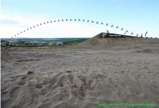 Image of mountain biker performing a jump
- Contact us for consulting inquiries.
- Downloadable spreadsheet (coming soon).
[