
It feels like time moves at its own pace sometimes. I started a project to model a stingray bike – those iconic bikes many of us rode before BMX became the dominant trend. And only now am I getting around to writing about it. Recently, while browsing the SolidWorks forums, I noticed a familiar pattern: a wave of new users asking many of the same fundamental questions that have been around for years. While some veterans are still active, the community’s atmosphere feels subtly different. But forum dynamics aren’t my focus today. My point is, there’s a fresh influx of people discovering the basics and the more nuanced aspects of design and modeling that might not be immediately obvious.
During the process of modeling the coaster brake hub assembly for this Bike Stingray project, I encountered several details that, while second nature to me now, could be valuable insights for these new SolidWorks users.
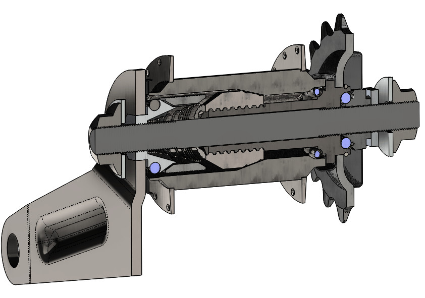 Diagram of a bike stingray coaster brake hub assembly modeled in SolidWorks, illustrating its internal components for educational purposes.
This model is intended for educational purposes and entertainment, so it might not be perfect in every detail or meet strict production standards. The goal was to complete it in about eight hours, which included understanding the mechanism’s operation, creating the parts and assembly, and ensuring everything fit together correctly. This assembly comprises 22 parts, 18 of which are unique. None are exceptionally complex individually, but a few presented some interesting challenges, and several incorporate noteworthy modeling techniques relevant to designing components for a bike stingray or similar projects.
Understanding the Coaster Brake Hub Mechanism of a Bike Stingray
The coaster brake is the braking system found within the rear hub of primarily budget-friendly bicycles, including many bike stingray models. It functions in three modes: braking when you pedal backward, driving the wheel forward when pedaling forward, and coasting when the pedals are stationary.
The most fascinating aspect of this mechanism lies in the brake shoes. These aren’t rigidly fixed to anything; instead, they float between components and are ingeniously wedged by angled surfaces against the inner diameter of the hub to generate braking force. If you aimed to simulate this assembly realistically in SolidWorks with mates, you’d likely need to employ contact or limit mates. This is because, in reality, these parts operate with a degree of freedom within the grease-filled space between the bearing cone, clutch cone, and hub. While the individual part geometry is simple to model, simulating the assembly’s dynamic behavior accurately would be a more complex task.
Modeling the Brake Shoes for a Bike Stingray in SolidWorks
To model the brake shoe, I started with a straightforward revolve feature to create the main shape. Then, I used another revolve to form the first groove on the outer surface, followed by a linear pattern to replicate the series of grooves. This process might seem simple, but many users often inquire about creating these kinds of fine details commonly found on real-world parts, especially when designing components for bikes like the bike stingray.
Constructing the Hub Assembly for a Bike Stingray
Another component that was conceptually simple but required some thought was the hub itself. The hub is actually modeled as a multi-body part. The spoke flanges are typically made from a softer metal than the main hub body. Because the braking and driving surfaces are integral to the hub, the central part of the hub needs to be made from hardened steel. Think about how often you used to slam on the brakes of your bike stingray as a kid – those braking surfaces need to withstand significant wear and tear. Hence, these parts are robust and heavy-duty. Conversely, the spoke connection points don’t require such hardness. Therefore, the flanges are often press-fit onto the hub body and are angularly offset to ensure even spoke spacing. This design also contributes to cost savings in manufacturing these more affordable bikes, including the classic bike stingray.
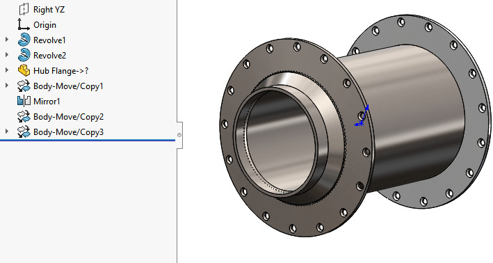 3D model of a bike stingray coaster brake hub assembly in SolidWorks, highlighting the hub body and attached flanges using inseparable subassembly technique.
The main hub body was modeled within the part file. The flange was then brought in using the “Insert Part” feature. It was subsequently positioned, mirrored/copied, and placed on the opposite side. This approach results in three distinct bodies within the hub part. This is a practical illustration of an “inseparable subassembly,” a modeling technique frequently used to create a single part appearance from multiple components using SolidWorks multibody capabilities.
The way you would handle this in a Bill of Materials (BOM) and engineering drawings depends on your role in the product lifecycle. If you are the original hub manufacturer, you would detail the flange as a separate part with its own part number and drawing, and the hub body likewise, with an assembly diagram illustrating the flange assembly process onto the hub body. However, if you are a wheel builder purchasing pre-made hubs for bike stingray wheels, you would likely only be concerned with a single part number for the complete assembled hub, irrespective of its internal construction.
Conclusion
If you have specific questions about any of these modeling techniques or the bike stingray coaster brake hub design, please leave a comment below. In future posts, I plan to delve into other parts of the hub assembly and then move on to modeling the frame of the bike stingray, exploring more interesting design and SolidWorks techniques along the way.
