
Stingray Bikes, those iconic predecessors to BMX bikes, hold a special place in the hearts of many. While the gears of time may turn slowly, the mechanics of these classic rides remain fascinating. Recently, while engaging in online forums, particularly within the SolidWorks community, it’s become apparent that a new generation is exploring foundational engineering concepts, often asking questions that resonate with seasoned professionals. This exploration is a great reminder of the enduring appeal of fundamental mechanical designs, like the coaster brake hub found in stingray bikes.
Delving into the construction of a coaster brake hub assembly reveals several principles that are often taken for granted, yet are incredibly insightful for those new to mechanical design or SolidWorks modeling. This article aims to dissect this mechanism, offering educational insights and entertainment for both novices and experienced enthusiasts.
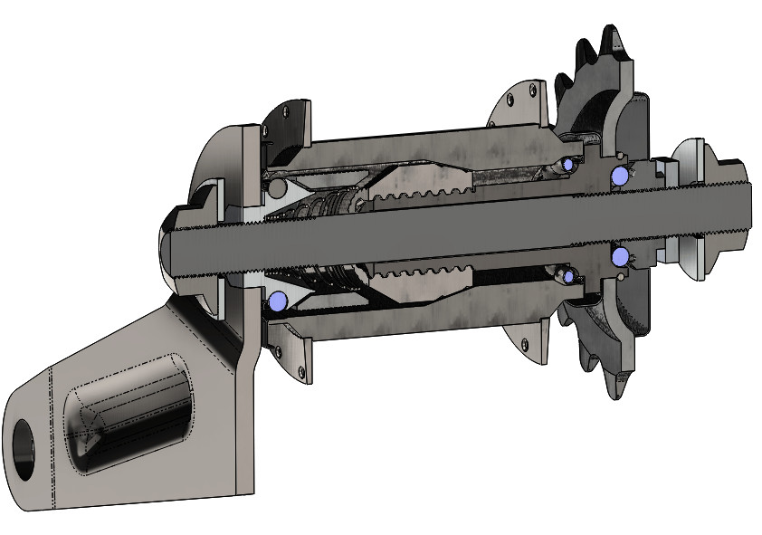 Exploded view diagram of a stingray bike coaster brake hub assembly, illustrating its internal components for educational purposes.
It’s important to note that the model discussed is primarily for educational and illustrative purposes. While striving for accuracy, certain details might be simplified or not perfectly aligned with strict production standards. The goal here is to understand the core functionality and modeling techniques within a reasonable timeframe – approximately eight hours were dedicated to researching the mechanism, creating parts and assemblies, and ensuring component fit. This assembly comprises 22 individual parts, with 18 unique designs. While none are exceptionally complex, some present intriguing design challenges and highlight valuable modeling methodologies.
The coaster brake, central to the functionality of many budget-friendly bicycles, is an ingenious mechanism housed within the rear hub. It provides braking when the pedals are backpedaled, propulsion when pedaled forward, and freewheeling when the pedals are stationary.
The most captivating aspect of this mechanism lies in its brake shoes. These components aren’t rigidly fixed; instead, they float within the hub’s internal space, nestled between components like the bearing cone and clutch cone. Upon backpedaling, angled surfaces within the hub cleverly jam these shoes against the hub’s inner diameter, initiating braking. For those aiming to simulate this functionality realistically in SolidWorks, utilizing contact or limit mates would be essential, as the parts operate with a degree of freedom within the lubricating grease. While modeling the individual parts is relatively straightforward, simulating the assembly’s dynamic movement presents a more complex challenge.
Modeling the brake shoes themselves involved a simple revolve feature to establish the primary form. Subsequently, a second revolve created the initial groove on the exterior, followed by a linear pattern to replicate the series of grooves. This process, while seemingly basic, addresses common queries among SolidWorks users regarding the creation of intricate surface details frequently encountered in real-world components.
Another component that demanded careful consideration, despite its apparent simplicity, was the hub itself. The hub is actually constructed as a multi-body part. The spoke flanges, for instance, are often manufactured from a less rigid metal compared to the main hub body. Given that the braking and driving forces are directly transmitted through the hub’s core, this section necessitates a hardened material to withstand repeated stress. Think back to childhood, aggressively applying the coaster brakes – these hub components need to be robust! Conversely, the spoke flanges don’t require the same level of hardness. Therefore, these flanges are often press-fit onto the main hub body, strategically offset angularly to ensure even spoke distribution and reduce manufacturing expenses in entry-level bikes.
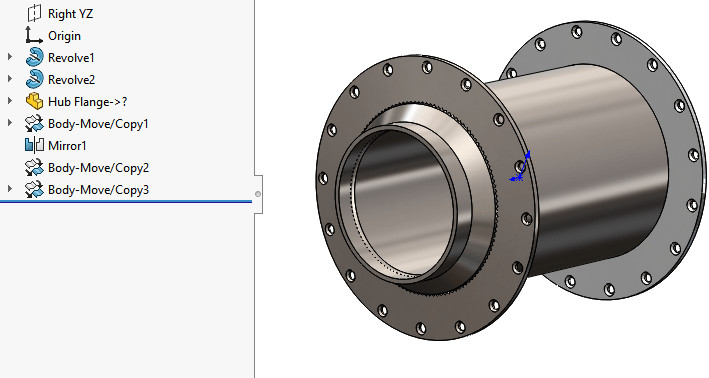 Close-up 3D model of a stingray bike rear wheel hub, showcasing the spoke flanges and construction details for SolidWorks modeling.
In terms of SolidWorks modeling, the main hub body was created within the part file. The flange, however, was incorporated using the “Insert Part” feature. This imported flange was then positioned, mirrored/copied, and placed on the opposite side of the hub body, resulting in a three-body part. This exemplifies the “inseparable subassembly” technique in SolidWorks, a common approach to represent a single functional component comprised of multiple parts using multi-body modeling.
The approach to representing this hub assembly would vary depending on your role. An original equipment manufacturer (OEM) would likely detail the flange and hub body as distinct parts, each with unique part numbers, drawings, and assembly diagrams illustrating the flange integration with the hub body. Conversely, a wheel manufacturer purchasing pre-assembled hubs would likely treat the entire hub unit, including flanges, as a single part with a single part number.
Should you have any questions regarding the specific techniques employed in modeling these components, please leave a comment below. This exploration of the stingray bike’s coaster brake hub is just the beginning. Future posts will delve into other fascinating components of the bike, starting with the frame, continuing to unravel the engineering ingenuity behind these classic machines.